After the PCB has been build we need to do some tests, before the GPS module is placed.
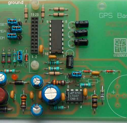
First of all, the jumpers should be set in these positions: RESET in pos. 2, NMEA in pos. 1, ROM in pos. 2, place ANT jumper and place SUPPLY jumper in pos. 2 because we test on 12 Volts.
You also need to make a cable for connecting the power supply on pin 7 (ground) and pin 8 (+ supply) of the RJ45 connector. See the cabling page for details.
Connect 12V on pin 8 and ground on pin 7 of the RJ45 connector. The LED
should light (there is only 1mA running through it) and you should measure the
following voltages between ground and:
pin 2 and 3 of the LT1107: +11,3V
pin 8 of the LT1107: +5,0V
pin 2-3 of the Supply jumper: +5,1V
pin 16 of the MAX232: +5,1V
pin 6, 14 and 7 of the MAX232: -9,5V
pin 2 of the MAX232: +9,5V
The power supply and rs232 level converter are now tested. You should be
able to vary the input voltage between 10 and 25V, and the 5V and 9,5V should
remain stable. Do not increase the input voltage above 27V since the input
transzorb will start conducting and blow the fuse!
Remove the power supply and put the GPS module on its place over the 4 PCB supports. Don't foret to remove the hooks of the plastic PCB supports, since it will be extremely difficult to remove the GPS module if you don't. While inserting, watch the 20-pin connector to slide smoothly into the connector on the PCB. Further tests should be made with the GPS module and an oscilloscope or a serial connection to a PC.
When you use the GPS kit on a 5V power supply, for example by feeding it via the Y cable from the USB or mouse port of your laptop, chack the voltage on the module (pin 2 of the 20-pin connector). It should be between 4,75 and 5,25V. The GPS module will not work below 4,5 V.
The very first tests can best be done by watching the NMEA data that is sent out to the serial port. Use the standard Hyperterm windows application or even better: install Teraterm. Communication is default done with 4800bd in readable ascii tekst en can be read quite well, if you recognise the patterns.
When the module is connected for the first time after a long period it should be
done with an external antenna and a clear view on the sky. Use Hyperterm
or Teraterm and set it for 4800bd / no par. / 8 data / 1 stopbit to see if the
receiver generates NMEA data. It should look like this:
$PRWIRID,12,01.80,11/26/97,0003,*42
$GPGGA,,,,,,0,00,,,,,,,*66
$GPGSA,,,,,,*42
..... etc. ....
When you see this pattern you can start another application like VidualGPS
or CSIGPS to see how the reception of the GPS satellites is. Depending on
a number of variables it can take a while before the receiver has determined his
own position. These variables are: