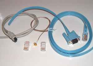
The cabling you need to make depends on the equipment that you are going to connect to the GPS receiver. We give an example here for connecting the GPS kit to a laptop for use on a navigational or routeplanner application line Route66, EasyTravelPro etc.
Other applications, like connecting to an organiser (PDA), APRS pcb etc etc will be added later.
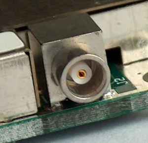
The antenna plug on the GPS module is a right angle MCX or OSX female plug. This is a stick-and-click system, with good rf specifications upto 5GHz.
If you have a GPS antenna with this connector you can use it directly - just drill a hole in the case at the exact position where the connector points to the case.
If you have another type of antenna connector, for example BNC or SMB you will need to make or buy an adapter cable. We offer a cablekit which contains amongst others a piece of teflon coax with a crimped-on male MCX connector. With this cable you can make your own adapter cable for connecting a BNC or SMB antenna.
In the Strapu case we offer with the GPS homebrew kit is enough place to mount a BNC chassis connector. The coaxial cable from the cablekit can be used for internally wiring the MCX from the module to the BNC connector you put into the case.
The MCX/OSX connector can carry +5V on the center pin to feed an active antenna. Place the "ant" jumper on the PCB for an active antenna, and remove this jumper if you connect a passive antenna.
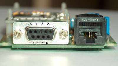
| contact | direction (GPS) | signal | level | description |
| 1 | output | CD | RS232 | wire selectable 1PPS |
| 2 | output | TXD | RS232 | NMEA data port output |
| 3 | input | RXD | RS232 | NMEA data port input |
| 4 | not connected | |||
| 5 | both | ground | 0 V | ground |
| 6 | output | DSR | RS232 | wire selectable 1PPS |
| 7 | not connected | |||
| 8 | output | CTS | RS232 | wire selectable 1PPS |
| 9 | not connected |
In RS232 terms the GPS kit is a "modem" device, which means that you use a normal 1:1 modem cable (DB9 male to DB9 female) to connect the GPS receiver to a PC or laptop serial port.
If you want to use the 1PPS (Pulse Per Second) pulse to achive very accurate time synchronisation of the PC's real time clock you need to solder a wire between the points "ps" and 1, 6 or 8 on the PCB, depending on the software driver's needs.
The DB9 connector is not nessecary - all signals are also available on the RJ45 connector. Therefore, on the pre-assembled PCB's the DB9 connector is not mounted, but separately delivered.
| contact | direction (GPS) | level | description |
| 1 | output | RS232 | 1 PPS signal on RS232 level. |
| 2 | output | RS232 | NMEA data port output. |
| 3 | input | RS232 | NMEA data port input. |
| 4 | output | TTL | 10kHz square wave locked to GPS timebase. |
| 5 | input | RS232 | 2e serial port for DGPS receiver. |
| 6 | output | TTL | 1 PPS signal on TTL level. |
| 7 | both | ground | ground, for both RS232 port and power supply. |
| 8 | input | supply | Supply. +5V regulated or +10 to +25V unregulated, depending on pos. of jumper SW5. |
Continue to the Cabling page.