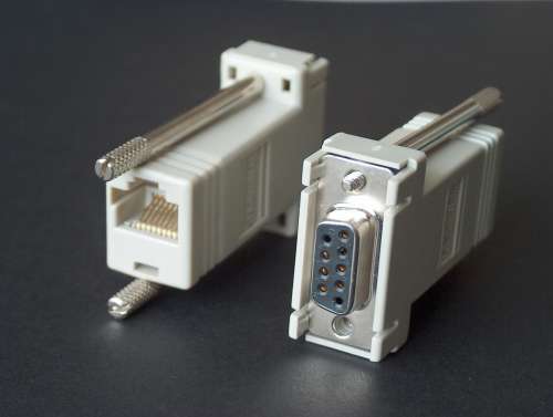
A cisco cable is meant to connect a pc or laptop to the console port of a Cisco device. The cable is a set containing these parts:
The original wiring of this Cisco cable with its DB9-RJ45 adapter is according to this table:
| signal (PC) | DB-9 adapter | color | RJ45 adapter | flat RJ45 cable | flat RJ45 cable | |
| (out) RTS | 7 | blue | 1 | 1 | 8 | |
| (out) DTR | 4 | orange | 2 | 2 | 7 | |
| (out) TXD | 3 | black | 3 | 3 | 6 | |
| ground | 5 | red | 4 | 4 | 5 | |
| ground | 5 | green | 5 | 5 | 4 | |
| (in) RXD | 2 | yellow | 6 | 6 | 3 | |
| (in) DSR | 6 | brown | 7 | 7 | 2 | |
| (in) CTS | 8 | white | 8 | 8 | 1 |
Notice that the flat RJ45 cable is a so-called "roll-over" cable, where 1 to 8 is connected with 8 to 1 respectively on the other end.
The RJ45 connector of the GPS kit is described here (only relevant signals shown):
| contact | direction (GPS) | level | description |
| 8 | input | supply | supply. +5V stab. or +10 tot +25V unstab. (SW5) |
| 7 | both | ground | ground |
| 6 | |||
| 5 | |||
| 4 | |||
| 3 | input | RS232 | NMEA data port input. |
| 2 | output | RS232 | NMEA data port output. |
| 1 |
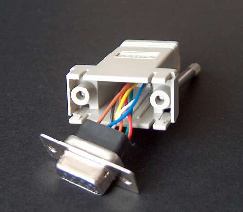
To create a cable with which the serial information can be transported to the pc's serail port and the power supply is inserted on the RJ45 cable the wiring inside the DB9-RJ45 adapter needs te be changed.
Prepare the USB or PS/2 cable by cutting it at the correct length (the distance between the USB or PS/2 port and the serial port of the laptop) and strip the cable in such a way that the 2 wires that contain the power supply are left over. (look here)
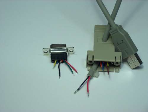
Make the following connections:
Use short pieces of thermal schrinking tube to isolate the joints, and use a tie-wrap over the supply cable to secure it in the adapter. Make sure the power supply jumper on the PCB is in the 5V position.
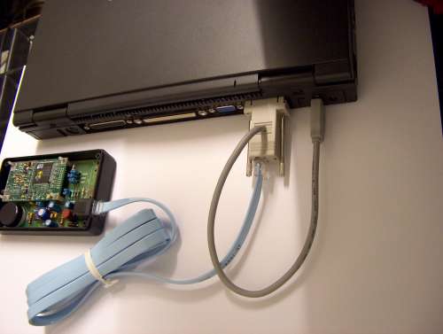
Double-check the wiring, and connect the cable to the laptop or PC and the GPS receiver. Check the supply voltage on the GPS module - it should be between 4,75 and 5,25V.